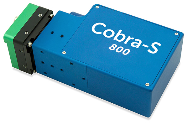
Your Cobra spectrometer is an essential component of a spectral-domain optical coherence tomography (SD-OCT) system. SD-OCT systems require spectral measurement of interferometric signals at very high-speeds. A Cobra spectrometer with its high sensitivity and high speed is ideally suited for this application. Cobra spectrometers receive light input via a single-mode fiber connected with an FC/PC connector. Dispersive optics in the spectrometer direct different frequencies or wavelengths to different pixels in the sensor. This provides spectral information about the input the light signal. The electrical output from camera is transferred to a personal computer using a camera link connection.
Data Flow
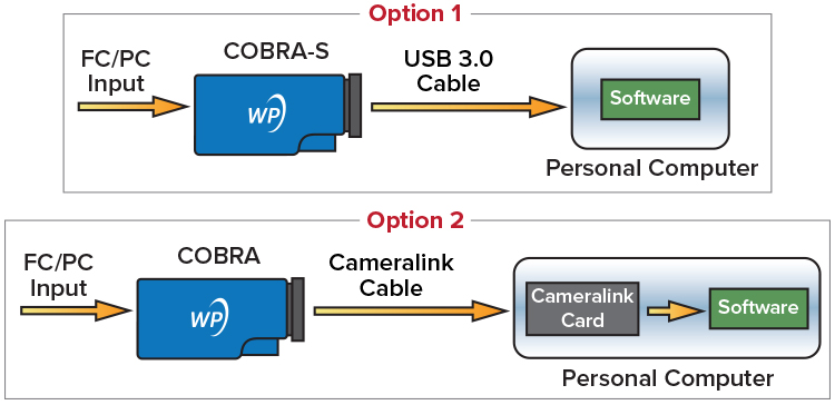
It is important to the make right choice of camera link card and software for your application. Cobra-S spectrometers have the ability to communicate directly with a personal computer via USB 3.0, but only at line rates of up to 130 kHz (option 1). All of our Cobra spectrometers can communicate with a personal computer using a Cameralink card and cable, including the Cobra-S at speeds of 250 kHz (option 2). Need help, a detailed manual for your specific camera sensor, or a new copy of your spectrometers’ system related files? Contact us
Camera: e2v
Camera Link Card: NI PCI-1433Cobra 1050, Cobra 1300, Cobra 1600
Camera: SUI GL-2048
Camera Link Card: DALSA LX1Cobra 1050, Cobra 1300, Cobra 1600
Camera: SUI GL-2048
Camera Link Card: NI PCI-1433Camera Link Commands and Serial ReferenceDownload manual
Setting up the Cobra OCT Spectrometer
This section provides generic instructions for setting up a Cobra spectrometer. Please note each model differs in shape, size and looks based on the selected configuration.
Step 1 Unpack items from the box that include Cobra Spectrometer and fiber optic cable. Based on choice of camera user will have appropriate power supply or a USB cable if the device USB powered. In addition user will have a sheet with a QR code and a cloud drive link where all relevant files are located. In certain cases user will receive another box provided by third party camera manufacturer.
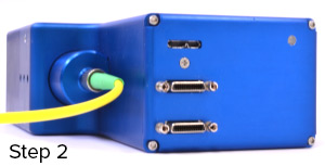
Step 2 Connect FC/PC end of optical fiber to the spectrometer as shown. Light should be introduced to the FC/APC side of the spectrometer using a mating connector.
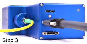
Step 3 Connect the smaller end of camera link cable(s), called SDR (Shrunk Delta Cables), to the spectrometer. Note in case the camera is being operated at a rate where medium or full camera link mode is used, two camera link cables are required.
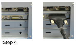
Step 4 Connect the larger end of camera link cable(s), called MDR (Mini D Ribbon), to the camera link card installed in your computer.
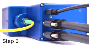
Step 5 If the camera is USB powered like the Cobra with a Wasatch internal camera, connect the USB micro type B connector to the spectrometer and USB type A side of the cable to the power. In case any other camera is used (such as Basler, Dalsa, SUI), connect appropriate power to the camera.
Step 6 Insert the power supply to the wall outlet (120-220 V/50-60 Hz).
At this stage the Cobra OCT Spectrometer has been setup and we are ready to test it with control software. Control software talks to the spectrometer via the camera link card.
Continue to the section tabs at upper left for further detail on specific hardware combinations.

Camera: e2v
Camera Link Card: NI PCI-1433
To test your Cobra Spectrometer with a National Instruments NI PCIe-1433 card, make sure that the card is installed in the PC and the Cobra spectrometer is connected.
Software Prerequisites
- NI LabView 2015
- NI Measurement and Automation Explorer
- e2v CommCam GeniCam
Wasatch Photonics Specific Configuration Files
The following file is required in order for NI MAX to communicate to the camera.
- e2v 2Taps.icd
 Configuring the Camera to Work with NI-Max

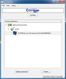
The camera must first be configured to have the same settings as defined by the ICD file linked above. To do this, launch CommCamm and then follow the prompts for an autodetect. If the device is powered and the cameralink cables are properly connected, you will see an image similar to the following image. Select the Octopus camera and hit the “Connect” button above the table.
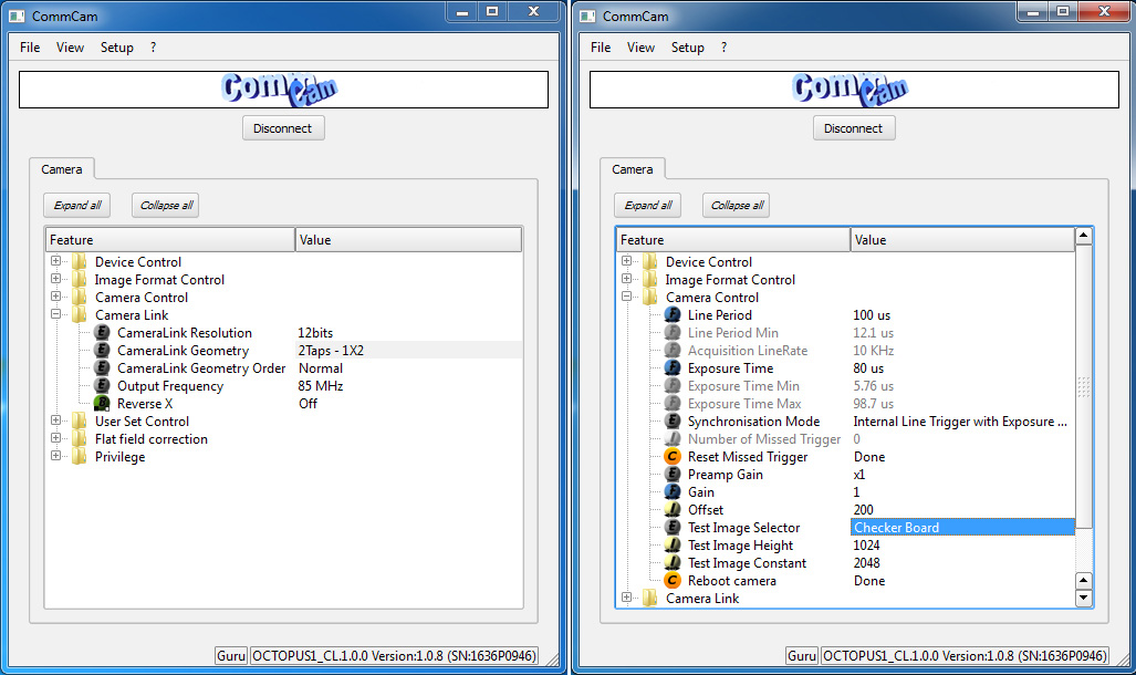
The default ICD file provided is configured for 2-taps, so we will need to verify this in the 2-taps mode and for the purposes of verifying operation, we will set the test image to be a CheckerBoard.
Measurement and Automation Explorer
Once the camera is configured to be in agreement with the supplied camera file, we can now retrieve our data through National Instrument’s Measurement and Automation Explorer (NI-MAX).
Launch NI-MAX and navigate to the connected camera. This will look similar to the image below.
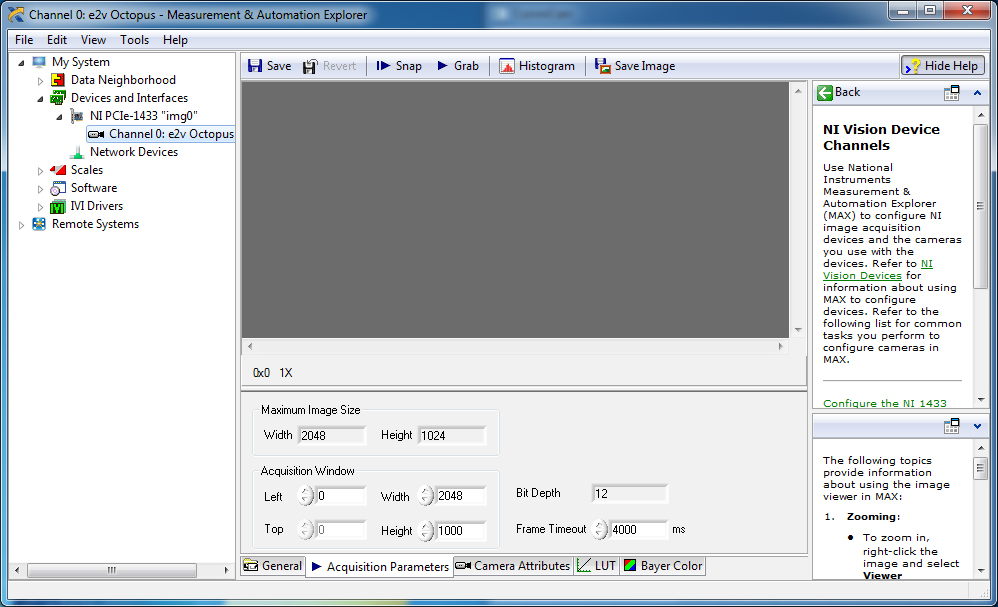
Right click on the connected camera “Channel 0” and load the supplied camera file by right clicking, selecting “Open Camera” and then selecting the ICD file.
Once done, you can now select the “Grab” button above the image and will now see the test checkerboard pattern begin scrolling in the window, similar to the image below.
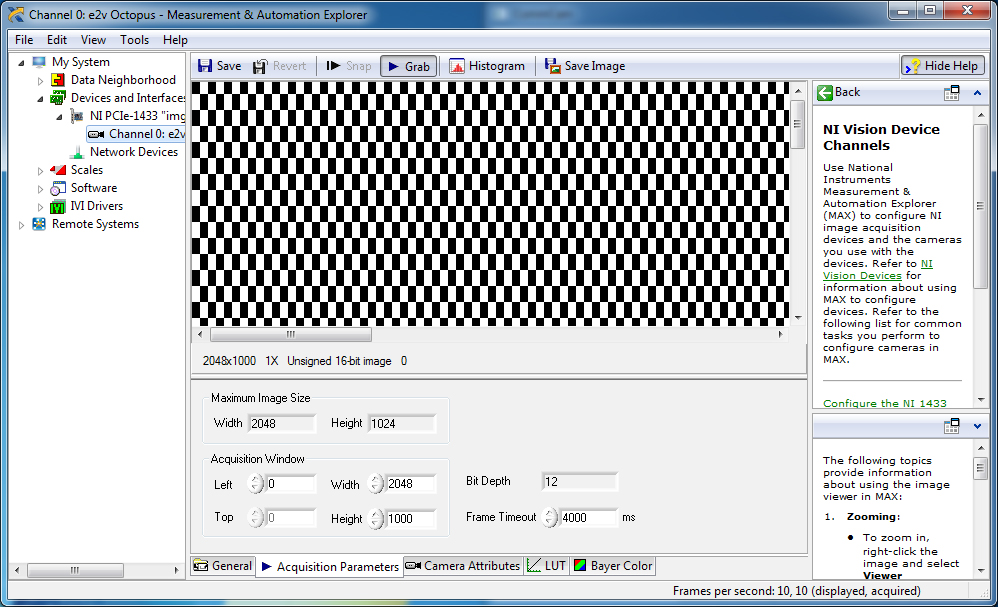
You can now go back to CommCam to disable the test image and begin using your spectrometer.
Camera: SUI GL-2048
Camera Link Card: DALSA LX1
To test SUI Camera enabled Cobra Spectrometer with Teledyne DALSA LX1 card make sure the card is installed in the PC and Cobra spectrometer is connected as described in the Setting up the Cobra OCT Spectrometer section.
Software Prerequisites
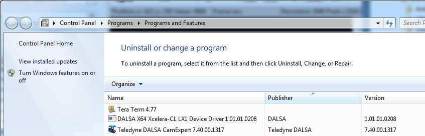 DALSA x64 Xcelera-CL version 1.01 or newer
Teledyne DALSA CamExpert 7.40 or newer
Wasatch Photonics Specific Configuration Files:
The following files are required, and are provided on an instrument specific configuration basis with your Cobra spectrometer.
- COBRA_SensorsUnlimited_2048.ccf
Look for the calibration information and configuration files for your particular instrument on the USB storage drive provided, or contact us for product support with your device serial number if these files are needed.
Sapera Configuration
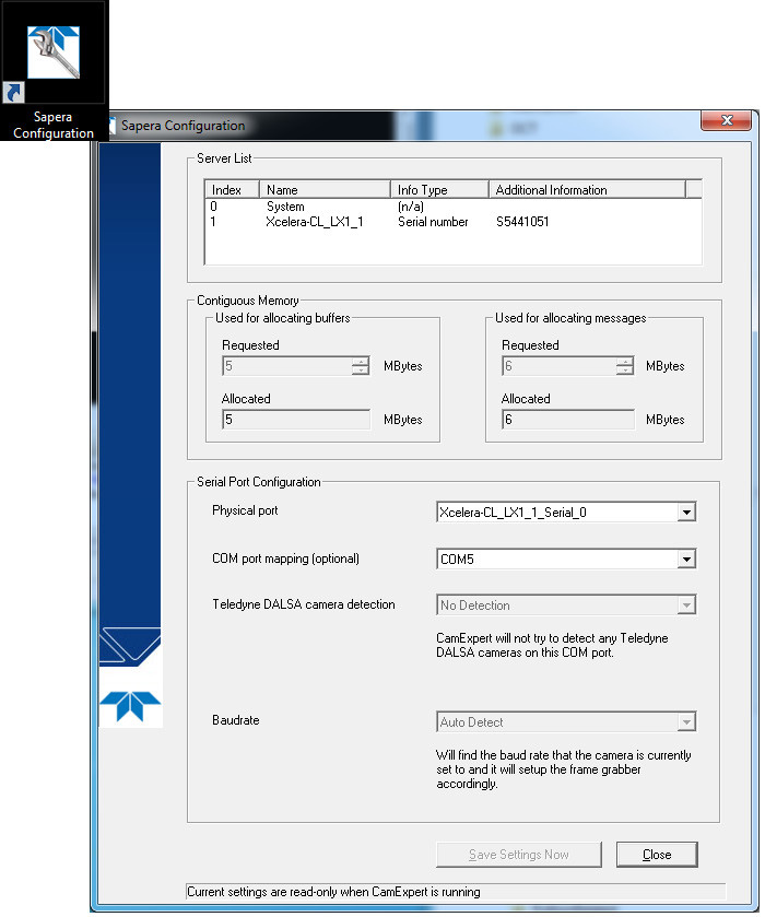
Start the Sapera Configuration program and assign the COM port for the camera link serial connection as shown. Reboot the computer for the serial port changes to take effect.
Important Note
Note that no serial configuration over camera link is required, as SUI cameras come from the factory pre-configured. They will automatically read from the sensor and put data on the camera link cable on power up.
CamExpert Visualization
1. Start the Sapera CamExpert Program.
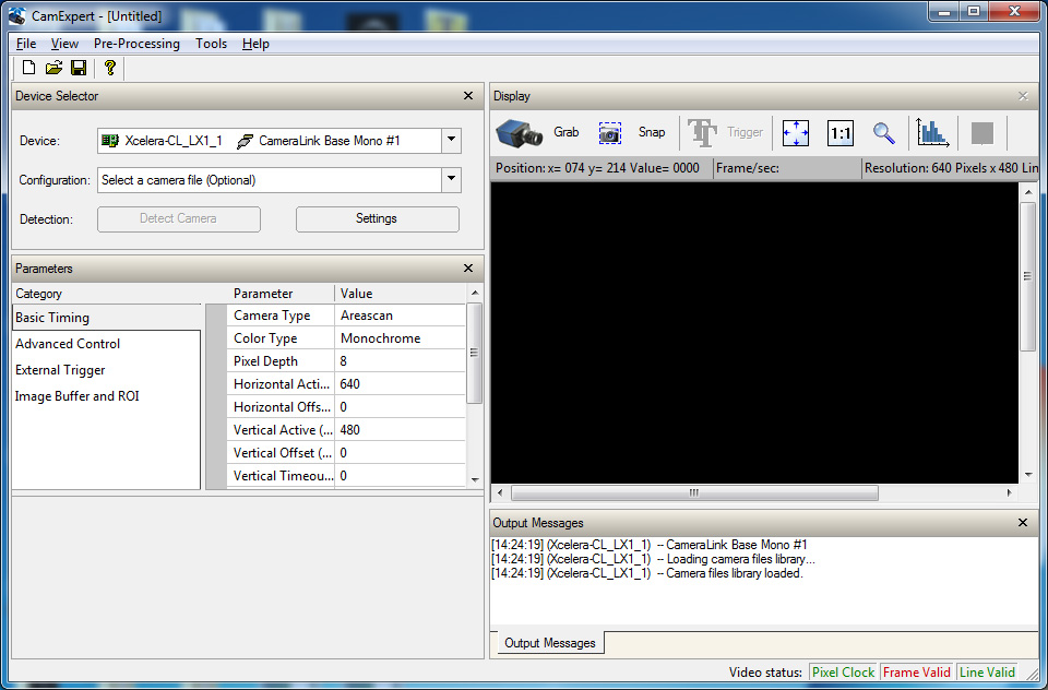 2. Load the previously downloaded Cobra_<model name>.ccf file under configuration dropdown menu.
3. Click the ‘Grab’ button.
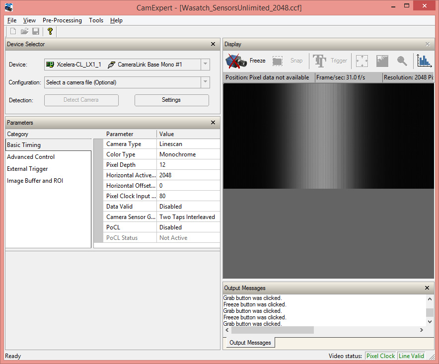
4. Click the Graph icon (at the far right of the icon bar), then choose the line profile option to verify that the spectrometer is returning high gain data.
 5. The image to the right is the spectral output shown after clicking the Graph Icon
Camera: SUI GL-2048
Camera Link Card: NI PCI-1433
To test Cobra spectrometer with National Instrument NI PCIe 1433 card make sure card is installed in the PC and Cobra spectrometer is connected as described in the Setting up the Cobra OCT Spectrometer section.
Software Prerequisites
- Labview 2012 64-bit
- NI-VISA Version 5.20
- NI Vision Acquisition Software VAS_August2012.
Wasatch Photonics Specific Configuration Files
The following files are required, and are provided on an instrument specific configuration basis with your Cobra spectrometer.
- GL2048L-10A_icd0170rev6.icd
Look for the calibration information and configuration files for your particular instrument on the USB storage drive provided, or contact us for product support with your device serial number if these files are needed.
Measurement & Automation Explorer
1. Copy the supplied GL2048L-10A_icd0170rev6.icd file into the ni-imaq\data directory. This is usually located under: c:\users\public\public documents\national instruments\ni-imaq\data
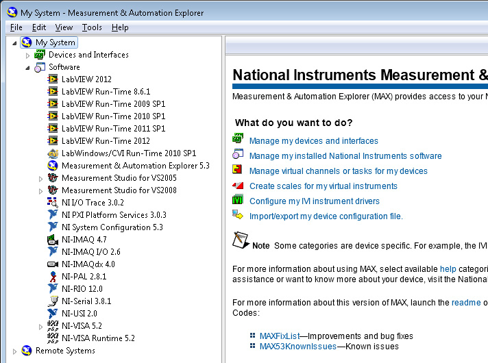 2. Start NI Measurement and Automation explorer, verify the software installation matches the screenshot shown here. As of this writing on 2015-04-09, the installation procedure has been tested with Labview 2012, NI-IMAQ 4.7 and NI-VISA 5.2. You may have different versions on your system. The versions shown the right are known to work on windows 7 and windows 8 systems.
 3. Expand the tree in the left hand side: My System -> Devices and Interfaces -> NI-IMAQ Devices -> img0: NI-PCI-1433 -> Channel 0:
As shown in the screenshot here, you may see the Basler A504k camera auto selected. This is the default camera .icd file selected during the National Instruments IMAX installation process.
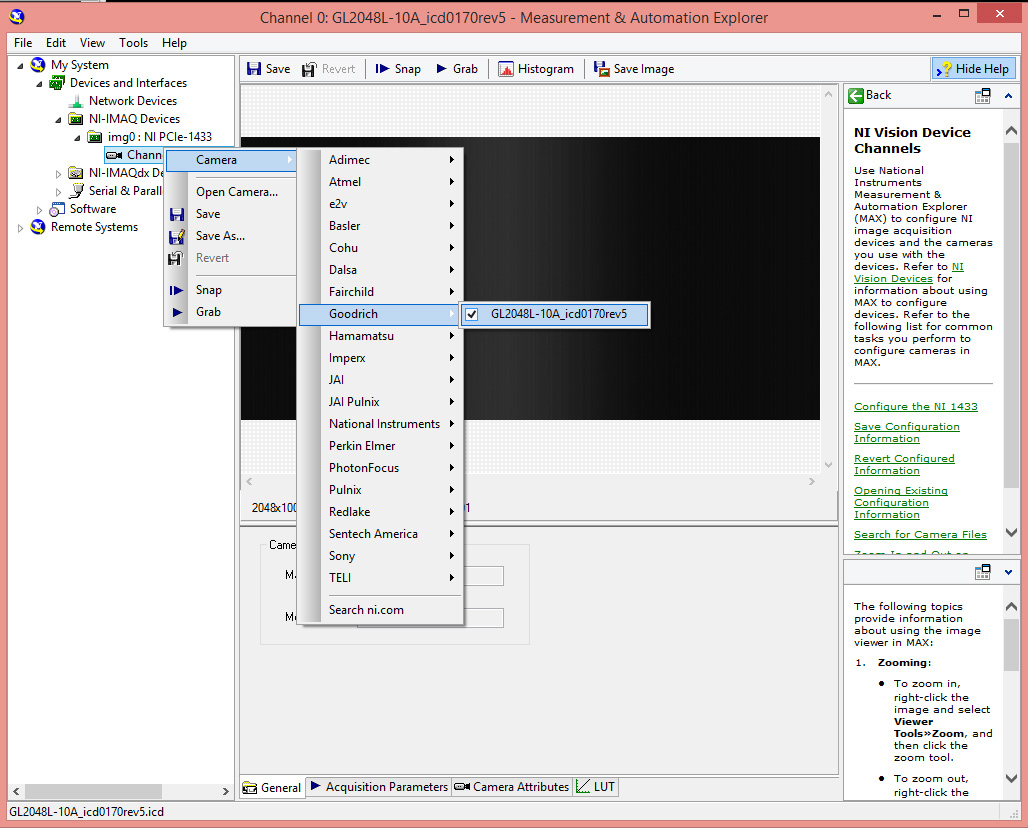 4. In step 1 above, the GL2048L-10A_icd0170rev6.icd file was copied to the NI IMAX icd file directory. To select that file for usage in IMAX, right click the Channel 0 entry, Go to Camera -> Goodrich -> GL2048L…rev6 file as shown in the image here.
Note that no serial configuration over camera link is required, as SUI cameras come from the factory pre-configured. They will automatically read from the sensor and put data on the camera link cable on power up.
 5. Click the Grab button.
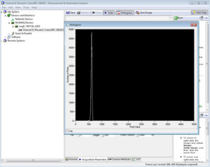
6. Click the Histogram button.
7. Click the ‘Save Image’ button, and save the file with a .TIF format.
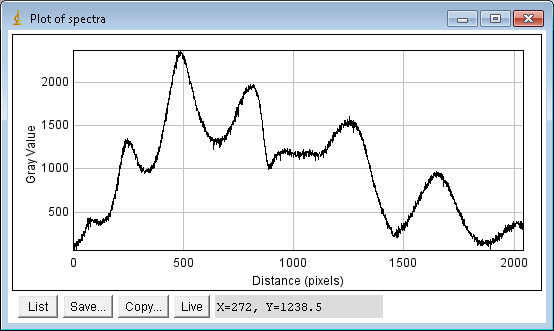 8. Open the TIF file in ImageJ, select a line of data in the image, click analyze->plot profile and you should see something like the following:
Cobra Camera Link Commands
The spectrometer camera board has an FPGA that provides control of the linescan array and sends out data via the serial port in the Camera Link board and cable.The spectrometer is designed to conform to the Camera Link standards for pinouts and I/O. The spectrometer has been tested with Camera Link cards from Dalsa and National Instruments, but any card that conforms to the Camera Link standards should work.
Camera Link Card Requirements
For the 2048 pixel arrays, base Camera Link configuration is used. This requires one Camera Link cable connected to the top connector (closest to the USB connector). For base Camera Link, the bottom connector is not used. The Camera Link interface should be configured for 12-bits per port with interleaved pixels.
Control of the spectrometer happens via the serial port on the Camera Link card. The following parameter values should be used for the serial communications:
- Baud Rate 9600
- Parity None
- Data bits 8
- Stop bits 1
For external triggering the CC1 line on the base Camera Link connector is used. Triggering should use LVDS values compatible with the Camera Link itnerface, with trigger pulses that are at least 1 microsecond long.
Typical Setup Procedure
The following command sequence can be used to start generating lines from the camera. This sequence uses internal triggering and generates A-scans at a rate of 10,000/second. Please see the following section for a detailed description of the commands.
init
gain 100
offset 0
int 90
ltm 100
lsc 1
NOTE: To stop generating lines, use lsc 0. Be sure to use an lsc 0 command BEFORE changing int, gain, or offset.
NOTE2: The above commands MUST be sent prior to image capture. The instrument does not gather data until an lsc 1 command is sent.
Serial Command Specification
Initialize
Command: init
Response: ‘<ok>\n’
Remarks: Initializes sensor registers; must be done before any other commands.
System Reset
Command: srst
Response: ‘<ok>\n’ if value is accepted. ‘<err>\n’ otherwise.
Remarks: Resets sensor.
Gain
Command: gain
Response: ‘<ok>\n’
Remarks: Sets the sensor gain. Range is 0 to 255. This command can be sent without a parameter to read the current value. Only integer values are accepted
Offset
Command: offset
Response: ‘<ok>\n’
Remarks: Sets the sensor offset. Range is 0 to 255. This command can be sent without a parameter to read the current value. Only integer values are accepted
Integration Time
Command: int
Response: ‘<ok>\n’
Remarks: Sets the integration time in microseconds. The valid range is 1 to 32,767 µs. This command can be sent without a parameter to read the current value. This should only be set when the camera is NOT scanning (i.e. after an lsc 0 command). The integration time must be at least 2 microseconds less than the line time (ltm).
Line Time
Command: ltm
Response: ‘<ok>\n’
Remarks: Sets the line time in microseconds. Valid range is 22 to 65,535 µs. The ltm must be larger than the integration time. This command can be sent without a parameter to read the current value. This should only be set when the camera is NOT scanning (i.e. after an lsc 0 command).
Trigger Source
Command: ats <0 or 1>
Response: ‘<ok>\n’
Remarks: Sets the trigger source. A value of 0 designates an internal trigger and a value of 1 designates an external trigger. The default setting is the internal trigger generated from the line time. This should only be set when the camera is NOT scanning (i.e. after an lsc 0 command).
Line Scan Control
Command: ltm <0 or 1>
Response: ‘<ok>\n’
Remarks: Line scan control. Set to 1 to start scanning, set to 0 to stop scanning.
Do you prefer working from a document? We’ve got you covered.
Download now